Considerations for the analysis of the interfaces of railway-based infrastructure
To assist the understanding of how, when, where, and why the interfaces occur, the AIR conceptual framework was developed through the practitioner and academic knowledge and experience of the lead AIR research investigator (Fig.3).
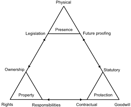
Fig.3: showing the AIR conceptual framework, which demonstrates the interconnected and interdependent nature of railway infrastructure with its surrounding environment, and third-party infrastructure. Source: Darroch, Beecroft, and Nelson, 2016.
The AIR conceptual framework
The purpose of the AIR conceptual framework is to assist the identification and clarification of multi-disciplinary data which explains the occurrences of the interfaces of railway infrastructure and its environment, as presented in Figs.1 and 2. Where that multi-disciplinary data include information related, but not limited, to:
- civil engineering (structural, geotechnical, etc.);
- legislation/statute;
- legal agreements (contracts, conveyances);
- historical and geographical contexts;
- asset management;
- transport and urban planning;
- project management;
- stakeholder management.
The AIR conceptual framework is formed of four triangles. The largest incorporates and is formed of the three smaller primary interfaces of presence, property, and protection, triangles.
The larger triangle represents the interconnectivity and interdependence of the primary interfaces (represented by the arrows on each side of the triangle). Where the primary interfaces of presence, property, and protection are encapsulating terms to describe where something is present, someone has a property interests in it, and the safe presence and operation of that infrastructure must be assured.
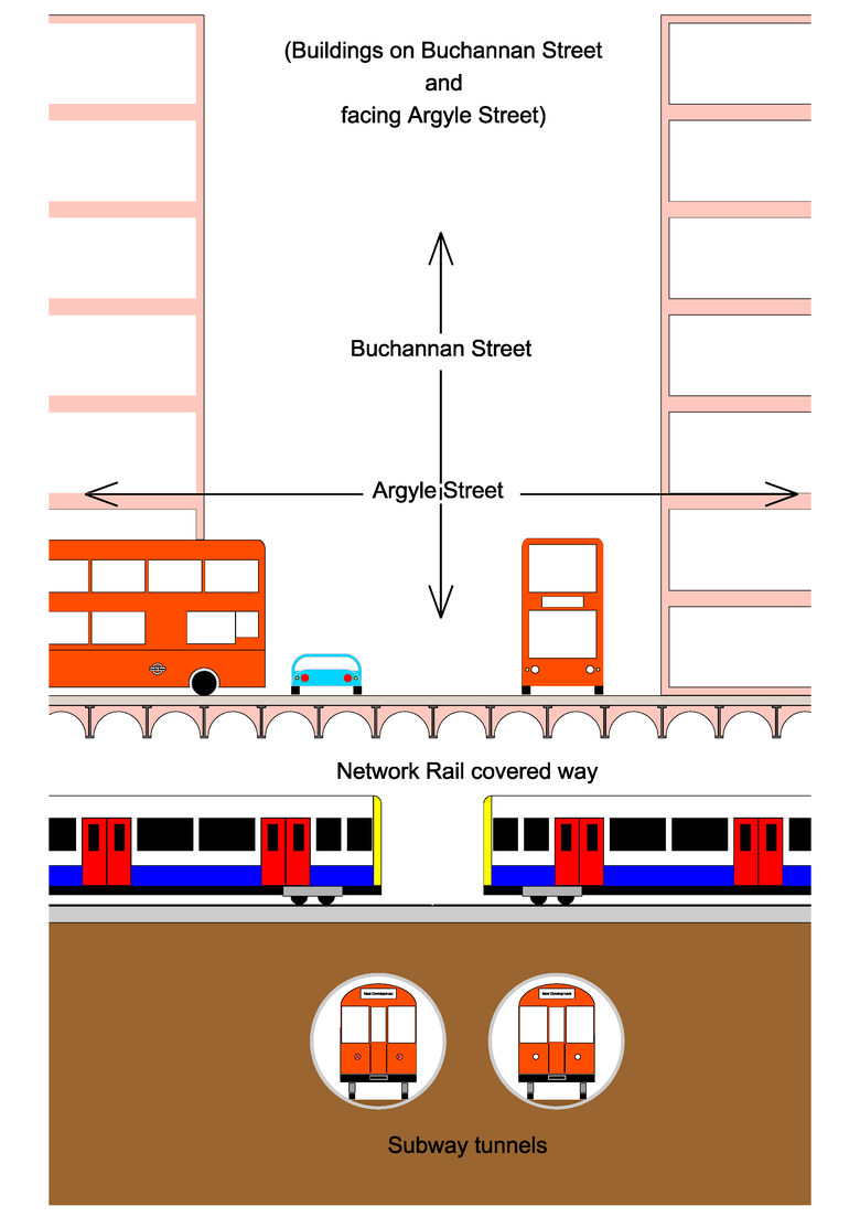 |
For example, Fig.4, is a simplified diagrammatic representation of the physical interfaces of a metro tube tunnels interfacing with a suburban main line railway in tunnel, above, which is located under a public highway and adjacent to buildings, at the junction of Argyle Street and Buchannan Street, within the centre of Glasgow, Scotland, UK.
To understand how, when, where, and why those interfaces occur, and what multi-disciplinary data may clarify the occurrence, sub-interfaces/enablers are shown within each of the primary interfaces. These are indicative of:
- what potentially enables the interface to occur - physical presence is enabled through legislation, which may also stipulate futureproofing for that physical presence;
- how, when and why the primary interfaces occur – the physical presence was enabled within the land of another stakeholder through purchase and subsequent ownership of land, or through a grant of right (easement/servitude), while the stakeholders within that scenario have responsibilities to ensure the safe presence and operation of one another;
- the types of inter-disciplinary data that may provide information on the interfaces between that UUMI and its environment - legislation enabled the purchase of land, which was clarified through a legal agreement, which imposed contractual protective provisions on that land to future proof the physical presence of the UUMI, authorised to be present through the legislation.
When the AIR conceptual framework is applied to analysis of the interfaces, therefore, it enables a user to determine what they must consider, sources of data (archives) which they may need to access, and what data may be beneficial to gather. These subsequently provide multi-disciplinary comprehension of:
- how, where, when and why the interfaces were created;
- their purpose and functions;
- how they create, effect, and affect, the interconnected and interdependent presence, property, and protection interfaces;
- how those interfaces must be managed, monitored, analysed, and diagnosed;
- how the interfaces are used, maintained, amended, and replaced; for their whole life cycle.
The need for a common shared understanding of the interfaces
It is not sufficient, however, for only one person or one team, within a railway-based organisation, to understand the occurrence of the interfaces. This is because, railway-based systems are managed and operated by many different disciplines, as demonstrated by the list of multi-disciplinary data, above. To ensure the safe effective, cost and time efficient management and operation of a railway-based system, therefore, knowledge of the occurrences of the interfaces must be shared across the organisation, and with its external stakeholders (third party infrastructure owners). Additionally, it is essential that all multi-disciplinary stakeholders, within and externally to the railway-based organisation, have shared methods of analysing the interfaces.
 |
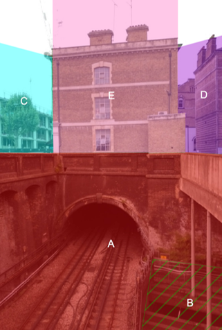 |
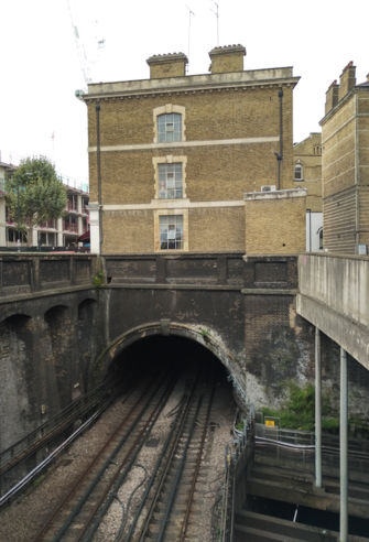
For example, Figs.5 & 6 show the presence and property interfaces of stakeholders where a building is located over a metro tunnel in central London, UK, shaded pink, and labelled E. The property interfaces are shown by shading and hatching representing:
- London Underground, the owner and maintainer of the metro infrastructure, shaded red and labelled A;
- beneath the metro infrastructure is urban main-line railway infrastructure, hatched green and labelled B;
- either side of the railway are public highway owned and maintained by:
- transport for London, shaded light blue and labelled C; and
- the London Borough of Islington, shaded purple, and labelled D.
To ensure the continued safe presence and operation for all the interfacing infrastructure within Figs.5 & 6, the stakeholders represented in Fig.6, must consider how their infrastructure is interconnected and interdependent with their surrounding environment and infrastructure.
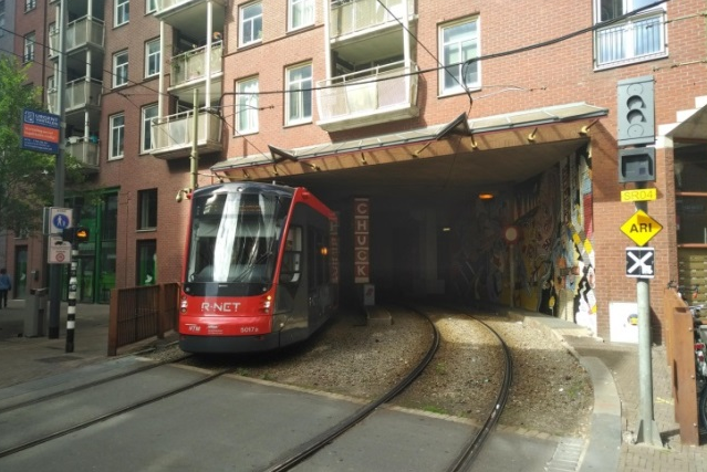
These occurrences of the interfaces are not just applicable to railway-based systems under or below ground, or just to the UK, where the initial AIR research was undertaken. They also apply to railway-based systems on the surface. For example, Figs.7 & 8, show the presence, property, and protection interfaces of a tramway in DenHaag, Netherlands, which are like those represented in Figs.5 & 6.
 |
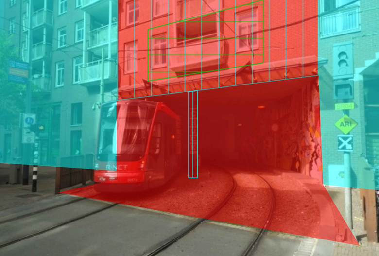 |
In Figs.7 & 8 are shown an urban tramway passing through an apartment block in central DenHaag, Netherlands. In Fig.8, the presumed property interfaces are represented by the different coloured shading and hatching, where:
- private ownership of the land and building is represented by blue shading;
- tramway owned land and airspace is shaded red;
- the right for the building, owned by the private developer, to be located within, on, and within the land of the tramway company, is represented by blue hatching.
To assist the understanding and management of the interfaces between railway-based systems, their surrounding environment, and interfacing infrastructure, and to assist the application of the AIR conceptual framework within railway-based infrastructure owning and managing organisations, the AIR research project was developed. The processes of which are described on the following page.